When you’re developing PLC code it can be difficult to test the behavior of the whole code, due to all the disconnected in and outputs. A colleague of mine found a nice solution how you can create a digital twin of the real machine. The digital twin then simulates the behavior of the real one. In this article I’ll show you how you can do this with a simple oven project.
- Example code: GitHub repo, direct download.
Different types of tests
There are different levels at which you can test your code, as shown in the image below. In this article I will focus on how you can do integration tests without the need for a real machine.
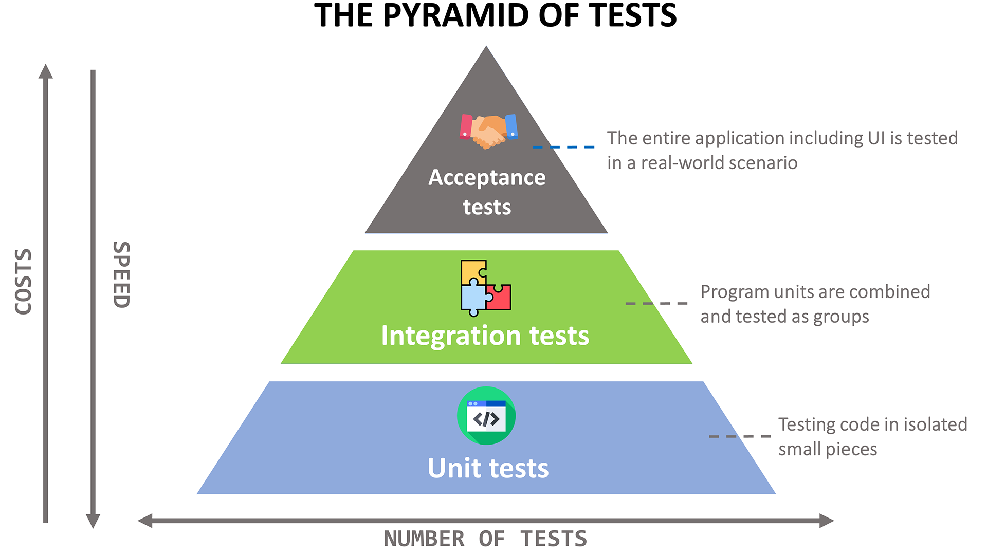
Image courtesy of AllTwinCAT.com
Unit tests
On the bottom of the pyramid are the unit tests. With unit tests you test individual functions and function blocks. For TwinCAT there are several options if you want to do this: TcProber, TcUnit.org and TcUnit. You can learn more about the first two libraries in this article on AllTwinCAT and about the last one on Stefan Henneken’s blog.
Integration tests
After testing the individual units, you want to make sure that once you glue several units together they work as intended. This is called integration testing. For this there aren’t that many well developed options that I know of.
One option is that you create an actual 3D model of your machine and connect that to your PLC as shown on the WJB Automation Blog. By using the 3D model you can easily check if parts are moving as intended and that there are no collisions. However, if you have a machine with less or no moving parts, this method is not an option. Furthermore it is harder to automate these tests further down the line.
The second option is to manually force different in/outputs in your program and verify that everything works as intended. This option is, of course, vey time consuming and not automated. And if you’re like me, than you didn’t become a software engineer to do things manually 😁.
The third and last option is to make use of Beckhoff’s EtherCAT Simulation module. This a quite extensive module (InfoSys):
The TE1111 TwinCAT EtherCAT Simulation function simulates an EtherCAT segment. An already created I/O configuration of the real plant is exported and can be imported into a second system as an ‘EtherCAT Simulation’ device. A mirrored process image is thus available on this system that can be linked with corresponding TwinCAT modules (e.g. written in the IEC 61131-3 languages or generated from Matlab®/Simulink®). The desired behavior of the machine must be implemented with sufficient accuracy in these modules.
When my colleague tested this, he didn’t quite get it to work for our machine. The simulation was having trouble simulating all the different terminals he thought. Long story short, that is why he decided to make a simpler version completely from scratch. Another small advantage, especially if you want to try this at home, is that you do not need a license to do this.
Digital twin?
What is a digital twin and why would you want one? Lets start with the why first. When you have your PLC project it has numerous in and outputs as visualized below.
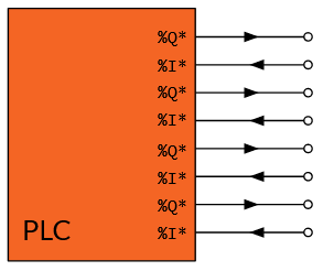
If you would like to do integration tests, or test your HMI, then it is often very difficult because the IOs are not connected. For example, you want to test some conveyer belt functionality, but you can’t turn it on because some safety latch is not closed.
That is where a digital twin comes in. A digital twin (or a TwinTwinCAT project? 😬) is a digital or virtual representation of your real machine. By making a digital twin we can mirror our IO’s and connect them to the original PLC project as shown here.
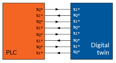
The twin can be made as detailed as desired. Components can be simulated just enough such that things can turn things on and off. Or individual terminals can be simulated, such that the failure of a single IO can be tested.
Once you have a working TwinTwinCAT project, it can be used to do (automated) integration tests. In this post I will not go into the automated tests. I will show you how to create a simple digital twin of an oven project. Perhaps I’ll do the automated tests in a future post.
Building a digital twin
Now I will guide you through how to build the digital twin project. I will only go into details on the relevant parts which are needed to get the twin working. The exact implementation of the function blocks you can see for yourself if you download the whole project’s GitHub repo or the direct download.
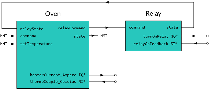
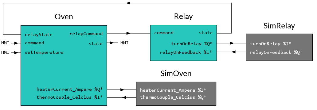
Below you see a schematic representation of the PLC project. The main part is the Oven function block. It takes a command from the HMI which can change its state. It also sends a command and receives a state from the Relay which will turn on the power of the heater inside oven. The oven sets the heater current based on the set temperature. Finally it receives feedback from the thermocouple about the measured temperature.
Creating a stand-alone PLC & HMI project
I’ve implemented the above functionality in a stand-alone PLC project. A stand-alone project has the advantage that it can be imported both into a digital twin TwinCAT configuration project as well as a real machine TwinCAT configuration. I recommend that you open the Oven.sln file located in DigitalTwin/Oven for this part. If you opt for this, you can skip to the next section.
To create the stand-alone PLC project from scratch you can:
- Open Visual Studio and Go to File > New > Project
- Select TwinCAT PLC > TwinCAT PLC Project
- Give it a name and location and click OK
- Then in the next window under PLC Templates select Standard PLC project
- Give it a name and click on Add.
- Add the POUs as desired.
Next we’ll add a HMI project to the stand-alone solution to get some visual feedback. To add the one I prepared, go to File > Add > Existing project and add the HmiProject.hmiproj found in DigitalTwin\Oven\HmiProject.
Creating the digital twin project
Now we are going to create the TwinTwinCAT project. Open a new Visual Studio window to create a new solution and go to File > New > Project. Choose TwinCAT Projects > TwinCAT XAE Project (XML format).
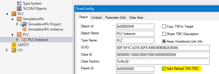
Add the oven stand-alone plc project by right clicking on PLC > Add Existing Item... Then navigate to the Oven PLC project. You can either add the PLC.tmc file or the PLC.plcproj. Note that the PLC.tmc only appears after the first successful build of the stand-alone project.
The advantage if you add the .plcproj file, is that you can directly edit the function blocks of the stand-alone project (the one in DigitalTwin/Oven/Oven/Oven.tsproj) from the digital twin project (the one in DigitalTwin/OvenConfig/OvenConfig/OvenConfig.tsproj). A disadvantage is that if you have the stand-alone project open, it will ask you to reload files every time you make a change. If you choose to go with the .tmc file option, you get neither the advantage nor the disadvantage.
If you select the .tmc file, make sure to select the “Auto Reload TMI/TMC” option. This option can be found under PLC Instance > Object. This will make sure that whenever the .tmc file of the stand-alone project changes, it will automatically be reloaded into the digital twin project. I used the .tmc file for this tutorial.
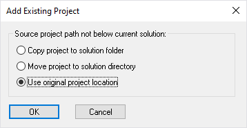
If you’ve selected the .plcproj file, then make sure to select “Use original project location”. With this option you can directly edit the PLC project from the digital twin project.
Next, add a new PLC project which will become our digital twin PLC project. Right click on PLC > Add New Item… and choose PLC template > Standard PLC project. Give it a name, e.g. SimulationPlc.
In the SimulationPlc project, rename the PlcTask to SimulationTask. This is to make a clear distinction between the PlcTask from the Oven project and the Simulation project.
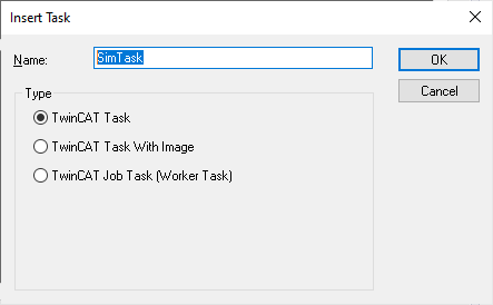
Then make a new task and call it SimTask.
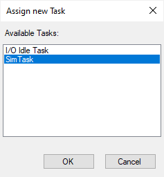
Next right click on SimulationTask and select Assign to task
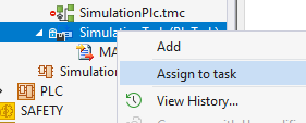
Then select the SimTask as the new task where SimulationTask will be assigned to.
Adding digital twin objects
In this section I will show you how you can create the digital twins of the Relay and Oven function blocks.
Mirroring the relay
The PLC project has a function block Relay which represents a relay. The relay has one output turnOnRelay AT %Q* : BOOL; which is set to TRUE if the relay needs to turn on. It then watches for the feedback of the relay if it actually turned on with relayOnFeedback AT %I* : BOOL;. If the relayOnFeedback is set to TRUE, Relay will switch to the on state.
Without a simulation project, the feedback will never go to true, so the relay will always be in state off or turning on. So that is why we get this:
Go get the correct relay behavior we will create a mirror object of Relay called SimRelay. SimRelay will have the mirrored I/O as Relay in the PLC project. I.e. %I* becomes %Q* and vice versa:
Relay |
SimRelay |
|---|---|
relayOnFeedback AT %I* : BOOL; |
➔ relayOnFeedback AT %Q* : BOOL;
|
turnOnRelay AT %Q* : BOOL |
➔ turnOnRelay AT %I* : BOOL;
|
For the implementation of SimRelay I added some delays before the feedback is set, in order to clearly see the state transitions in the HMI. The complete codes is then as follows.
FUNCTION_BLOCK SimRelay
VAR
    relayOnFeedback AT %Q* : BOOL;
    turnOnRelay AT %I* : BOOL;
    relayOnDelay : TON := (PT:=delay);
    relayOffDelay : TOF := (PT:=delay);
END_VAR
VAR CONSTANT
    delay : TIME := T#1S;
END_VAR

relayOnDelay(IN:=turnOnRelay);
IF relayOnDelay.Q THEN
    relayOnFeedback := TRUE;
END_IF

relayOffDelay(IN:=turnOnRelay);
IF NOT relayOffDelay.Q THEN
    relayOnFeedback := FALSE;
END_IF
Next we create an instance of the SimRelay and call it every cycle in the MAIN program of our simulation project.
PROGRAM MAIN
VAR
    simRelay : SimRelay;
END_VAR

simRelay();
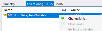
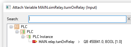
Now we can link the instance of Relay in the PLC project with SimRelay of the simulation project. To do so, double click on SimulationTask Inputs and right click on MAIN.simRelay.turnOnRelay and select Change Link….
Then select the relay output from the PLC project.
Do the same with the SimulationTask Outputs, where you can link the MAIN.SimRelay.relayOnFeedback to MAIN.Relay.relayOnFeedback. Then you reactivate the configuration and you should see the oven go from on to off via the turning on and off states.
Mirroring the oven
Now the oven can be turned on, but it doesn’t heat up if a temperature is set. In order to make this work we need to create SimOven. In this function block I again take the mirrored IO of the Oven one. Then to simulate gradual heat-up, I’ve used some exponential smoothing. The filter takes 99.5 % of the temperature of the previous cycle and adds 0.5% of the new temperature. The temperature is calculated by the current squared as per Joule’s first law. The limit is added to prevent the temperature from going below room temperature. The complete code is as follows.
FUNCTION_BLOCK SimOven
VAR
    thermoCouple_Celcius AT %Q* : REAL;
    heaterCurrent_Ampere AT %I* : REAL;
END_VAR
VAR
    previousTemperature : REAL;
    filterParameter : REAL := 0.995;
END_VAR

thermoCouple_Celcius := previousTemperature * filterParameter
    + LIMIT(20, TO_REAL(EXPT(heaterCurrent_Ampere, 2)), 1E5) * (1 - filterParameter);
previousTemperature := thermoCouple_Celcius;
After making an instance of SimOven in MAIN and linking the IOs of the simulation project with the PLC project we get a working oven! 🎉
Discuss: r/TwinCAT.